
Digital Grounding Device and the Hazards.
- VIDYUT SURAKSHIT BHARAT ABHIYAN
- Sep 10, 2023
- 7 min read
This article explains about a non standard device used in Industries especially for computer, telecom and control system called as Digital Grounding Device and the hazards related to its use.
Electrical safety in LV installations
Current flowing through the protective conductor (earth wire) during normal condition is always a threat to electrical safety in LV installations. Continuous current flowing through protective conductor creates accidents such as shock, arching, and fire, hence no compromise is allowed in the regulations and standards to the provision of protective earthing and equipotential bonding, to safeguard the equipment and personnel.
Although functional earthing is essential to ensure reliable operation of sensitive devices and electronic gadgets, the subject is misinterpreted as difference between Neutral and Protective Conductor, as a result the electronic system industry demand a low potential difference between N and PE and the complete confusion starts at this point.
Following safety measures are mandatory in all electrical installation to avoid risk to the occupants:
Minimum Insulation resistance between Live conductors (line and neutral together) and protective conductor is 1 MΩ as mentioned in CEA regulations, and all IS code of practices.
Maximum PE Conductor Current in equipment (not due to a fault in a.c system) is as per Table 1. Additional safety measures like reinforced insulation of equipment, safety extra low voltage system, reinforced equipotential bonding etc. shall be necessary when the limits prescribed in the Table1 are exceeded.
Isolating device having a leakage current across open poles, exceeding 6 mA per pole is determined as the end of its life.
TN-C system is not allowed inside a building with electronic installations (refer clauses from IS732 mentioned in this article)
Rated current of equipment | Maximum PE current |
0 to 2 A | 1mA |
2A to 20 A | 0.5 mA/A |
Higher than 20 A | 10 mA |
Table 1: Example of PE conductor current in permanently connected equipment
(Ref Table 4 of IEC 61140 or clause 5.4.3.6 in IS732.
Measures shall be implemented to ensured NIL/Minimum protective conductor current (continuous leakage current) during normal condition to avoid hazards.
Neutral and earth shall be separate downstream the point of commencement of supply to maintain a minimum insulation resistance of 1 MΩ as stipulated in regulations and standards. Inappropriate connection of neutral and protective conductor downstream the main distribution location, will lead to partial neutral current flow through the protective conductor. Electrical installation shall avoid this neutral circulating current, if not, is certainly a violation of electrical safety.
Quote from IEEE142 “In a commercial or industrial building the neutral or grounded circuit conductor is connected to ground at the service equipment (main panel) and at the secondary side of a separately derived system (isolation transformer). It is not unusual to find the branch circuit distribution panel neutral bus bar connected to the metallic panel frame (ground), which is a violation of the NEC. One study showed 20% of the neutral conductors accidentally faulted to ground in circuits supplying lighting fixtures. With multiple connections of the neutral conductor to ground on the same power system, a portion of the load current flowed on the equipment grounding system to which the electronic equipment was referenced. This current flow transferred voltages into the grounding system of the electronic equipment, causing errors or worse”. |
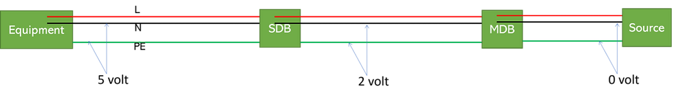
Neutral to earth voltage – a case study.
Due to the unbalance in load (due to single phase loads), Neutral current existed in the installation where the case study is made. The Neutral current varies depending upon the variation in connected load current, which produced a voltage between 5 and 8 volts between Neutral and PE conductor.
Neutral to earth voltage – Is it a problem???
There is an apprehension within the electronics engineers that the voltage between neutral and earth creates malfunction and failure in electronic equipment, as a result engineers working in the field of electronic equipment always recommend a voltage less than 1 V (or 2 V) between neutral conductor and earth conductor of the location.
The assumption of neutral to earth voltage creating failure to electronics and the nonstandard mitigation techniques adopted to avoid this voltage do not have any technical ground, however often end up with increasing the problem.
Concept of Functional Earthing and Protective Earthing.
Electronic equipment may need functional earthing for its reliable operation. In such case the manufacturer shall provide a facility as below,
Class 1 electronic equipment which require functional earthing shall have separate Protective Earth terminal (PE) and Functional Earth terminal (FE). Protective earth terminal is connected to the casing or exposed conductive parts of the equipment and Functional earth terminal is connected to the operational voltage reference point of the equipment (e.g. to the PCB of the equipment)
Class 2 and Class 3 equipment doesn’t require protective earthing, but functional earthing may be required.
It is the responsibility of the manufacturer to provide proper marking based on the safety / functionality requirement in the terminals of those equipment as mentioned in fig. 2

Class 1 equipment may require separate terminals with symbols 5018 and 5019, depending upon its design. Class 2 and Class 3 equipment doesn’t require Protective Earth but Functional Earth may be required. In such case, appropriate markings shall be included in the product. This means the manufacturer while designing, manufacturing and testing the product shall decide requirements of reference potential for electronics and provide such provisions. While installing the buyer shall ensure a perfect reference for the FE terminals, by implementing appropriate bonding topologies. Finally FE and PE are connected at "one place", to avoid circulating current through Functional Earthing and Functional Bonding networks. (Note: common bonding network is also possible.)
The above arrangement ensure that the voltage between neutral and PE conductor is irrelevant. Remember in an IT system (unearthed system) with distributed neutral, the voltage between N and PE can be up to L to N voltage during normal operation and L to L voltage during first fault. Electronic systems shall be installed to handle these voltages.
Misunderstanding: Neutral to earth voltage is due to poor neutral earthing. |
Fact: Neutral to earth voltage is due to continuous current flow and the resistance of neutral conductor. Note: The above fact is applicable to the subject which is discussed in this article. |
False claim of Digital Grounding Device (DGD) as a solution to reduce N and PE voltage:
The device called Digital Grounding Device or Intelligent Grounding Module is used in places where electronic devices are installed, especially in Telecommunication sites, Control and Process plants and Industrial automation to reduce the voltage between N and PE.
The Device and the Claim:
The Digital Grounding device at the location where the study is made consists of a plastic box, with 3 phase input through a 2.5 sq.mm. long wire, a busbar mounted outside the box which can accommodate about 10 connections of M8 Bolt and a surge counter (as in fig 3). The supplier claimed that these devices doesn’t require connection to an earth electrode. In addition, it is claimed that this device will eliminate the potential between Neutral and PE conductors in the installation. It protects the connected electronic device against harms from Neutral to earth voltage, problems due to earthing and from transient and lightning surges. At the outset it looks like a fantastic solution for solving multiple problems faced by the electronic and telecommunication installation.
According to the manufacturer, internally the device consists of electrodes which dissipate the current from neutral, nullifying the current. As a result, the Digital Grounding Device reduces the voltage between Neutral conductor and PE conductor in an electrical installation. It is also a mandatory condition that this device is used within 5 meters close to the equipment.
An e mail from the manufacturer claims the following, Dear Sir, Here is a brief idea about the meaning and Utility of Digital Grounding Device. We, a solution providing company for many sensitive electronics and electrical equipment like servers, PLC drivers, etc. and to protect them to get damaged due to any unexpected surge in power supply. As you know Generally we Ground the Neutral with Earth at the Transformer output to save the Transformer in case the Neutral fails and to ground the Leakage current which at times travels up to Transformer if it is too high for any reason like a short circuit or any other abnormality. In most cases, the Critical load Like Drives, PLC & Server racks are kept far away from the transformer. Due to this the impedance of the Ground gets too high, so the leakage current at this point, instead of traveling to the ground near the transformer, will Travel to phase or neutral as per Current Characteristic, find the Easiest Path & will add into the Input Current/Voltage and this will either increase the Heat or harmonic inside the Circuit. Most Sensitive Devices like PLC & Computer racks operate on DC between 24 Volt to 5Vdc & leakage current/Voltage in Ac Circuit is always higher than this. Which is the major reason for the failure of the PLC Address Bus & Computer/Server Motherboard Databus. Our Device will prevent 100% leakage current to travel back to the input of PLC/Rack & provide the shortest & easiest path for leakage current to get dissipated & convert into Heat. This technology has been used widely by Boeing Aircraft, NASA, ISRO & Signal Core Div. of the Indian Army supplied by our principal company DSS to Provide the Shortest path to the leakage Current without burying the copper rod in the earth near the Load. Benefits of DGS are as follows, 1. Battery Life of UPS:- It resolves the problems of frequent failures of the battery in every 2 years, the reason the leakage current couldn’t get ground properly due to a distant Earthing from equipment. In the Data Centre UPS gives DC supply to the battery for charging up through DC Bus Bar or duct. As we know the power supply in computer applications works on 5 VDC or 24 VdC . Their internal circuitry is inductive and Capacitive to both loads i.e. produces leakage current. If this current doesn’t get ground irrespective of any reason it hits back to the circuit means in the UPS output. This AC leakage current or voltage is having more magnitude than 5v or 24v, hence it will add to the output of UPS and fed to the battery mixed with the dc current. Now with the input of ac and dc current, Battery Anode Point gets hardened and hardens gradually and after a point of time, loses its potential. An effect of this UPS starts giving supply to the battery finding low potential and the result of this battery starts swelling up. While putting DGS to the UPS we can ground the leakage current there only without propagating it further while maintaining GN voltage permissibly. Hence it will inc Battery life as well additionally. 2. Surge Protector:- It works as an effective 100% Surge Protector and after this there is no need to put any further A, B, or C type of Surge Protector. Any Surge protector works on Earthing credibility but if Earthing is not successful then there remains no meaning of putting SPD irrespective of its class. 3. Failures of Earthpit:- As we know Earthing depends on some of the factors to give its mean to the dissipating Current ie GN Potential should be less than 0.9V. These factors are 1. Climate 2. Soil Resistivity 3. Distance of our equipment Got Earthed (from pit to equipment) 4. Material has been used inside it (Conductor) The above factors play a very important role to achieve the proper result. In any case, we can be stabilized in two equations but we can't make any control on climate and the distance of equipment and Earthpit ie length of down conductor which enhances the impedance of ground causes risen of GN Voltage which emphasizes the reverse current to hit back to the internal circuit as mentioned above. As an outcome, Earthing cannot be a successful and effective solution for the equipment that requires a nominal GN Voltage. Technology Details:- To understand the technology comprehensively you need to go through the write up attached as PPT herewith. In layman's terms please have a look at some points below. DSS is using the same technology used in Earthing but without burying a rod inside the ground. Ø There is an electrode inside similar to conventional earthing, length has been maintained while putting knobs on it to increase the surface area. Ø There is a chemical gel inside it similar to Chemical Earthing and for the same reason. Ø There are some LC Circuits inside to prevent the equipment from Surges. Ø It filters the harmonics at 5%. Thanks & regards, |
In practice, the device has 3 lines + neutral as input, connected by a 2.5 Sq.mm wire through 63 amps 4 pole MCB as shown in fig 3. It has a busbar mounted outside the box, where all earth conductors from nearby equipment are connected.

The Installation
The typical installation where the case study is made, the device is installed closer to control panel of a process machine. This device reduced the voltage between Neutral and Earth conductors to almost 0 V. While inspecting it is found that, the neutral and earth conductors are shorted inside the device.
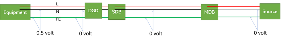
Fig 4: N to PE voltage after installing Digital Grounding Device (DGD) in the line
The Digital Grounding Device interconnected the N and PE internally. As a result, the lines upstream up to the transformer become TN-C. Partial neutral current was flowing through the earth conductor and through all nearby metal objects.
Electricity supply combining PE and Neutral inside consumer premise is not allowed in all known IS / IEC/IEEE standards and may lead to.
Electrical shock due to voltage and continuous current flow through metallic parts of the building.
Fire due to sparks in the building due to undesired continuous current flow through metal parts.
EMC issues (e.g. Communication devices will malfunction and fail)
Quotes from IS732 4.5.4.4.3.1 It is recommended that TN-C systems should not be maintained in existing buildings containing, or likely to contain, significant amounts of information technology equipment. TN-C-systems shall not be used in newly constructed buildings containing, or likely to contain, significant amounts of information technology equipment. NOTE — Any TN-C installation is likely to have load or fault current diverted via equipotential bonding into metallic services and structures within a building. 4.5.4.4.3.2 In existing buildings supplied from public low-voltage networks and which contain, or are likely to contain, significant amounts of information technology equipment, a TN-S system should be installed downstream of the origin of the installation (see Fig. 31). In newly constructed buildings, TN-S systems shall be installed downstream of the origin of the installation (see Fig. 31). 4.5.4.4.3.3 In existing buildings where the complete low-voltage installation including the transformer is operated only by the user and which contain, or are likely to contain, significant amounts of information technology equipment, TN-S systems should be installed (see Fig. 32). 4.5.4.4.3.4 Where an existing installation is a TN-C-S system (see Fig. 33), signal and data cable loops should be avoided by
|
The electronics system suppliers (such as BMS, UPS, VFD's) often demand a low potential difference between N and PE (e.g. less than 1 volt). This demand is mainly due to the unawareness of the subject by the electronic system supplier or products which do not conform to the standards.
Nonstandard means of mitigation like dedicated earth electrode, interconnecting neutral and earth downstream the mains incoming, camouflage the situation temporarily but create danger to the occupants.
Providing multiple earth electrode with a low resistance does not have any role in reducing the neutral potential.
Claims of DGD are as an effective Surge arrester, limit voltage due to reverse current and it measure earth electrode resistance. DGD is a Surge Protector (240 kA surge arrester): DGD is a monitor to measure earth electrode resistance: |
The supplier of DGD are good in marketing and selling the products, but very poor in technical subjects and often unaware of the basics of electrical safety.
Higher lead length of an SPD: Higher lead length create more voltage drop in the connecting wires, resulting inefficient protection. In the case where the study is made, the lead length of SPD was more than 5 meters, as a result the device cannot be considered as an affective surge arrester, even if an MOV exist inside the casing. In contrast this device could be a possible source of fire and accident in the industry (e.g. 2.5 sq.mm conductors protected by a 63 Amps MCB) .
MOV’s in a surge protector are supposed to end the life in short circuit. These devices require protective measures against internal short circuit. However, the 2.5 sq.mm wires and the 63 amps MCB mismatches this requirement. This is also a possible cause of fire.
The electronic system supplier blame poor earth electrode resistance as the reason for failure.. Often users expect a low resistance earth electrode in soil as the only solution for all problems. Hence it is a great idea to monitor this resistance continuously, if possible online. However, the fact “earth electrode resistance to soil doesn’t have any role in safety and reliability of an electrical or electronic system in an LV installation” is rarely known. The manufacturers utilise this unawareness and supply fancy products with large claims.
Conclusion:
Neutral to earth voltage is due to neutral current from unbalanced/single phase loads.
DGD could create serious safety hazards due to neutral circulating current (electrocution and fire) anywhere in the premise.
Components used in DGD is a potential hazard and could ignite fire.
DGD as a device to reduce voltage between N and PE will lead to disaster, hence it is strongly recommended to disconnect this device if used and to ensure a minimum insulation resistance of 1 MΩ between N and PE conductors.
Digital grounding is a baseless propagation of eliminating neutral to earth potential, could become a dangerous practice if adopted.
Electrical Inspectorates of the respective states shall BAN these dangerous and nonstandard products.
S. Gopa Kumar
President
National Federation of Engineers for Electrical Safety
Member
IEC TC64 MT3, MT12, MT40, MT41, PT60364-8-3, WG43.
TC 81 (Lightning protection) MT 3, MT 14, WG 18, AHG 19, MT 21.
SC 37 A (SPD’s) WG03 & 05.
Syc LVDC WG 01.
BIS NBC-2016, ETD 20, ETD 30 & ETD 50


Comments